Bleed margins and rounded corners
A bleed margin is an extra margin around the outside of a component design. The component’s graphics extend out of the intended design area to cover the bleed margin as well. This allows some wiggle room when the components are cut out with less than perfect precision.
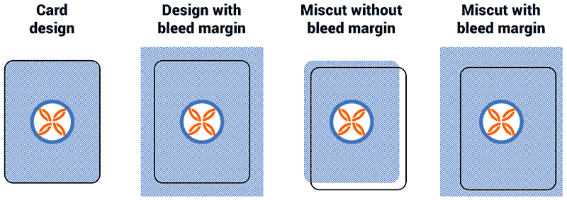
For best results, the bleed margin should be built into the component’s design. When this is not possible, Strange Eons can usually synthesize a bleed margin that will be “good enough” on the fly.
Building a bleed margin into the design
To include a bleed margin in a component’s sheet design, you need to provide a larger template image that includes the content to appear in the bleed area. To do this:
-
Decide on the bleed margin size. This is measured in points and will be the same on all sides. Typical bleed margin sizes in the publishing industry are 3 mm (8.5 pt) or 1/8” (9 pt). The standard size in Strange Eons is 9 pt.
-
Ensure that the template image takes the bleed margin into account. You must extend the design by the margin size on all four sides, keeping the “true” design in the centre of the image.
You will need to calculate how many pixels to add based on the resolution of your template image. For example, if your template image is 150 ppi (pixels per inch), then for a 9 point bleed margin you need to add 9/72 × 150 = 19 pixels to each side. (Round up to the nearest whole pixel.) A template image that was 225 × 300 pixels becomes 263 × 338 pixels.
-
Set the bleed margin size for each sheet. This lets Strange Eons know how much to exclude when the user does not want a bleed margin, amongst other uses. This can be done in the following ways:
- Add a
-bleed-marginsetting key with the same base key name as the face’s template image. Set the value of the key to the bleed margin width in points. - For DIY (scripted) components, you can set the margin size in the component’s
createfunction. For example,diy.bleedMargin = 9;would set a 9 pt margin. Setting a margin in this way will override the value for all of the component’s faces. (Use the setting key method if different values are needed for different sheets.) - For compiled components, you can override the sheet’s
getBleedMargin()method to return the desired margin in points. By default this method returns 0 unless the setting key is defined.
- Add a
To change or remove the margin in a future edition of the component’s plug-in, set the margin in both create and onRead. Setting the margin to 0 will remove the bleed margin; this is also the default.
It is possible for the user to request a bleed margin with a non-standard size. In this case, if your design includes a margin, it will be trimmed down or additional margin will be synthesized as needed.
Simulated bleed margins
When the user requests a bleed margin that is larger than the designed bleed margin (or there is no designed margin), Strange Eons can generally synthesize a a simple bleed margin on the fly. Since machine cuts are not generally off by more than a millimetre or so, the faked margin rarely stands out. You can exercise limited control over the synthesized margin as follows:
- Compiled components can override the
isMarginSynthesisAllowed()method to explicitly allow or disallow bleed margin synthesis. - Calling a sheet’s
allowTemplateUseInBleedSynthesis()may improve the margin quality in many cases. Margins are synthesized in one of two ways: If a quick check suggests that the sheet has a solid border, then the border is extended. Otherwise, the border is synthesized by pasting mirrored copies of the painted sheet image into the margin area. By calling this method, you allow the template image to be used for this mirror process in addition to using the final, painted image. This excludes text and other painted content from the margin area.
Bleed margins cannot currently be synthesized on components with transparent faces.
Rounded corners
Some components, including most card decks, are meant to have rounded corners, like those shown in the bleed margin example image above. Strange Eons will show faces with proper round corners when View/Edge Finish/Rounded Corners is selected. Round corners are added to a face by setting a corner radius, measured in points. You can set this value in one of the following ways:
- Add a
-corner-radiussetting key with the same base key name as the face’s template image. Set the value of the key to the desired radius. - If creating a DIY (scripted) component, call the DIY object’s
setCornerRadius(radiusInPoints)method. This will set the initial corner radius for all sheets, overriding the setting key. - Call the
setCornerRadius(radiusInPoints)method of the relevant sheet(s) once they are created. This can be used to set the radius on any sheet, but it is temporary and will not be saved with the component.
The Developer tools plug-in includes a tool, Cut Corners, that lets you experiment interactively with the corner radius feature.